
Shear Moment Calculator
Shear force and bending moment diagrams are the starting point for sizing any beam. Set the span and supports, add your loads, and this calculator solves the reactions and draws both diagrams, marking the maximum shear and moment — with deflection too if you enter the material and section properties.
- Free to use
- No sign-up
- Runs in your browser
Shear and moment calculator
Beam Analysis Template Pack
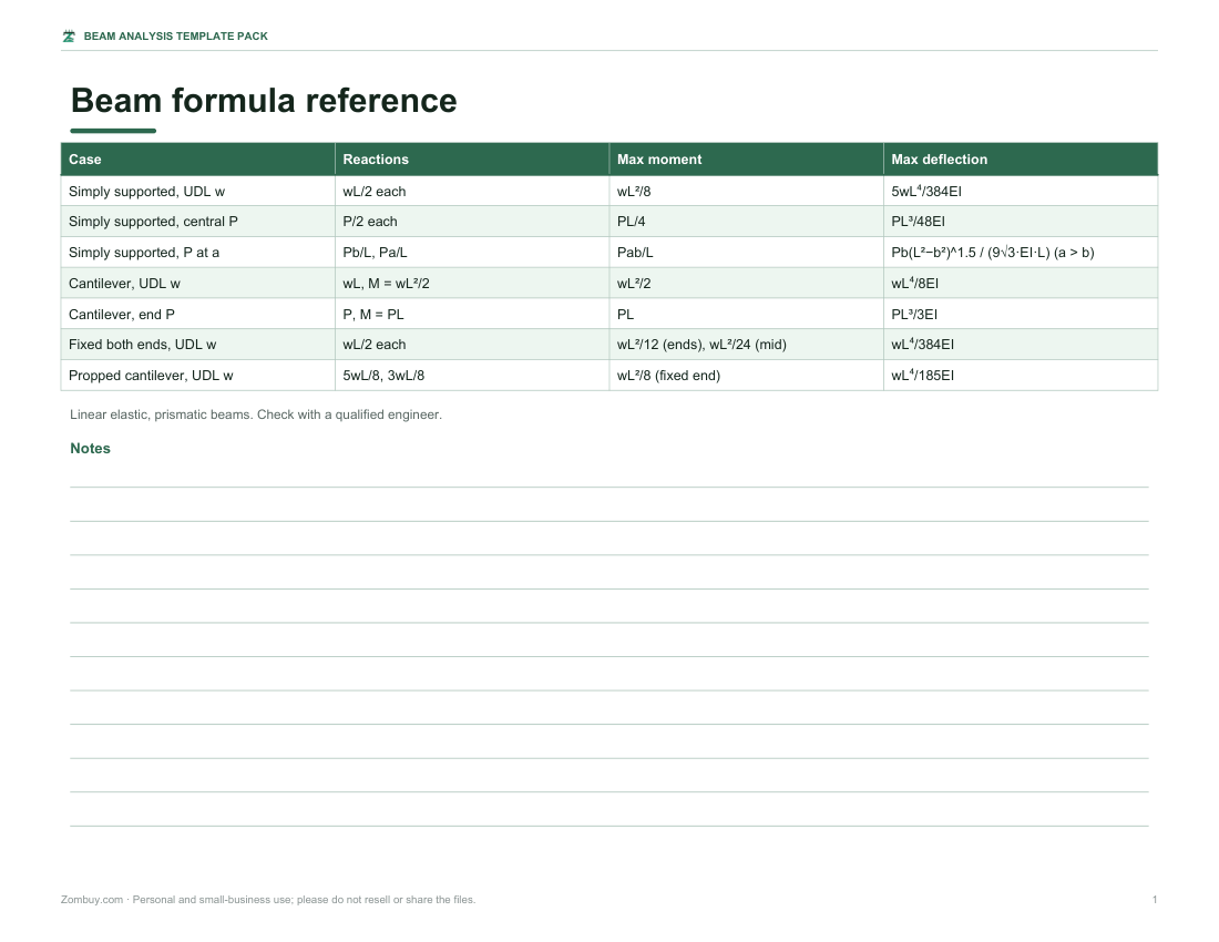
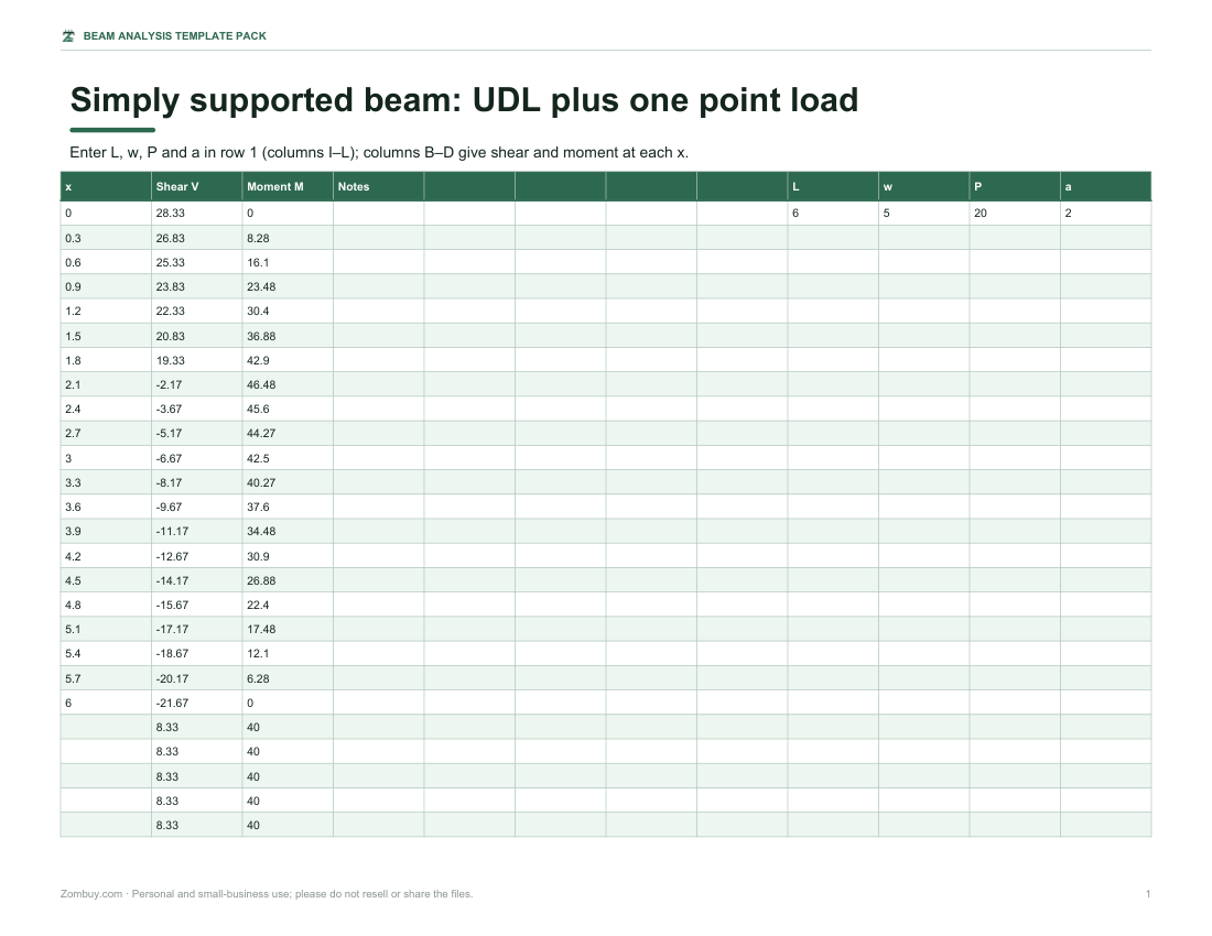
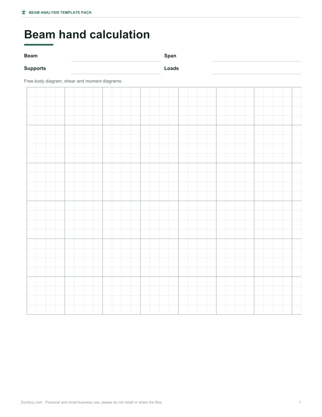
Beam formula reference sheet, an Excel beam worksheet with reactions, shear and moment at 20 points, a hand-calculation worksheet, a section properties table and a load take-down worksheet.
- Beam formulas (PDF/DOCX)
- Beam worksheet (XLSX)
- Hand-calc worksheet (PDF)
- Section properties (PDF/DOCX)
- Load take-down (PDF/DOCX/XLSX)
Formats: PDF, DOCX, XLSX. Instant download after payment (link valid 72 hours, up to 5 downloads). AI-assisted: the templates were drafted with AI help and reviewed and laid out before publishing.
$5.00 USD, one-time 5 files · about $1.00 each
- Instant download
- 7-day refund
- Secure checkout by Stripe
7-day money-back guarantee. Full refund within 7 days of purchase, even after you download.
Free sample: Beam Formulas (PDF, 122 KB)
Full refund within 7 days — see the refund policy and license.
Free printables
Single sheets you can print right now, no sign-up. The full pack adds every sheet in one download plus the editable files.
 Printable Beam Formula Reference
 Printable Beam Shear and Moment Worksheet
 Printable Shear Moment Calculator Worksheet
 Printable Section Properties Chart
 Printable Load Take-Down Worksheet
What shear and moment diagrams show
Shear force at a point is the sum of the vertical forces on one side of it; bending moment is the sum of their moments about that point. Plotted along the beam, the shear diagram shows where the beam is most likely to fail in shear (near supports and heavy point loads) and the moment diagram shows where bending stress peaks. The key relationships: the slope of the moment diagram equals the shear, so maximum moment occurs where shear crosses zero; a point load makes the shear jump; a distributed load makes the shear slope and the moment curve.
Worked example
A 6 m simply supported beam carries a 20 kN point load 2 m from the left support and a uniform load of 5 kN/m along its full length. Total load is 50 kN; taking moments about the left support gives a right reaction of 21.67 kN and a left reaction of 28.33 kN. The shear drops from 28.33 kN, crosses zero at the point load, and the maximum moment is 46.67 kN·m at 2.00 m — the same values the calculator shows with its default loads.
Standard beam formulas
| Case | Max shear | Max moment | Max deflection |
|---|---|---|---|
| Simply supported, UDL w | wL/2 | wL²/8 (midspan) | 5wL⁴/384EI |
| Simply supported, central point load P | P/2 | PL/4 (midspan) | PL³/48EI |
| Simply supported, point load P at a (b = L − a) | Pb/L or Pa/L | Pab/L (under load) | see calculator |
| Cantilever, UDL w | wL | wL²/2 (fixed end) | wL⁴/8EI |
| Cantilever, end point load P | P | PL (fixed end) | PL³/3EI |
Loads combine by superposition: the diagrams for several loads are the sum of the diagrams for each load alone, which is exactly how the calculator adds them.
Overhangs and cantilevers
Moving a support in from the end creates an overhang. Loads on the overhang lift the far support and create negative (hogging) moment over the support, which puts the top of the beam in tension — important for reinforced concrete and for timber joists with notches. A cantilever has a single fixed support that resists both force and moment; its maximum moment is at the fixed end.
Checking your answer
- The reactions must add up to the total load (vertical equilibrium).
- The shear diagram should return to zero at the right-hand end.
- The moment should be zero at a pin, roller or free end, and equal the fixed-end moment at a fixed support.
- The maximum moment should fall where the shear crosses zero, or at a support.
- Compare with a standard formula for the simplest version of your case.
Point loads versus distributed loads
A point load represents something concentrated — a post, a wheel, a machine foot — and produces a sudden step in the shear diagram and a sharp corner in the moment diagram. A distributed load represents something spread out — floor loads, snow, the beam’s own weight — and produces a sloping shear line and a curved moment diagram. Real loads are often a mix, and a partial distributed load (from and to positions) lets you model loads over only part of the span.
From moment to beam size
Once you know the maximum moment, the required section modulus is S = M ÷ allowable bending stress (or M ÷ design strength in limit-state design). For the worked example, 46.67 kN·m with an allowable stress of 165 MPa needs S ≈ 283 cm³, which points to a small steel I-section; a timber beam needs a much deeper section because its allowable stress is lower. Shear capacity, deflection, lateral buckling and bearing at the supports must also be checked — the diagrams here are the first step, not the whole design.
Deflection
Enter the modulus of elasticity E and second moment of area I to plot the deflected shape. In SI, enter E in GPa (steel ≈ 200, softwood ≈ 8–12) and I in cm⁴; in US units, E in ksi (steel ≈ 29,000) and I in in⁴. Deflection limits such as span/360 for floors are common serviceability checks — the calculator shows the ratio L/Δ.
What’s in the template pack
- Beam formula reference sheet (simply supported, cantilever, fixed and overhanging cases)
- Excel beam worksheet: reactions, shear and moment at 20 points with a chart
- Printable hand-calculation worksheet with free-body diagram grid
- Section properties table for rectangular and I-sections
- Load take-down worksheet
The calculator is free; the pack is a one-time download.
AI-assisted content
This page and the templates were drafted with AI assistance and reviewed before publishing. They are for education and preliminary checks — structural designs must be checked by a qualified engineer against the applicable codes.
Frequently asked questions
How do I draw a shear force diagram?
Start at the left end, add upward reactions, subtract downward loads, and plot the running total along the beam.
Where is the maximum bending moment?
Where the shear force crosses zero, or at a support or fixed end for cantilevers and overhangs.
What is a UDL?
A uniformly distributed load, such as a floor load, given per unit length.
What is hogging moment?
Negative bending that puts the top of the beam in tension, typical over supports and at fixed ends.
How do I check the reactions?
They must add up to the total load, and moments about any point must balance.
Can I model an overhang?
Yes — place the supports inside the beam length, for example at 0 and 4 m on a 6 m beam.
Which units should I use for E and I?
GPa and cm⁴ for SI, or ksi and in⁴ for US units.
Does it include self-weight?
Only if you add it as a distributed load.
Is the pack a subscription?
No, it’s a one-time download.